Like many people on Earth, I love stargazing and imagining all the possibilities that lie in the vast expanses of the universe. As a gearhead, tech nerd and maker I have taken that fascination and tried to express it through astrophotography. Until recently, I've been able to get increasingly clear, bright, and awe-inspiring shots just by improving my technique using tools I already have. Now, however, I have encountered a new foe: physics.
There's a lot of physics going on when you look at the stars. Fusion is releasing huge amounts of EM radiation from distant clumps of gas. Those waves travel through the vacuum of space, are bent by gravity, dispersed by vast clouds of gas and illuminate countless worlds. Our planet rotates on an axis while orbiting the Sun, which is caught in a milky whirl pool that floats lazily amongst trillions more. It's all quite messy, really!
Most of that stuff doesn't matter for astrophotography because exposures are typically short - from a few minutes to a few hours. The translation of the Earth over that period does not change the appearance of the sky, but one thing - the Earth's rotation - has a huge effect.

A lot of photons are needed in order to capture an image of a faint object in the sky. That means a lot of time spent photon-hunting (or gathering, whichever you prefer). And with the Earth spinning right round at 360 degrees per day, it won't be long until your star is smeared right across the image. This became my limiting factor, so I decided to build a solution.
Star Trackers
Star trackers are devices used to counteract the rotation of the Earth so long-period observations of the sky can be performed. The concept is simple: make a platform that rotates against the Earth at the same rate. Designs for star trackers range from Ford Pinto to Rolls Royce, and there are plenty of resources online about how to make your own. My design is of the "barn door" type, and is inspired by these projects: Makezine: 6 DIY Star Trackers for Perfect Night Sky Photos
In my build I add positional feedback so that the tracker can correct its motion over time - allowing (in theory) for increased precision.
Hardware
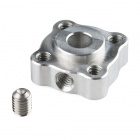
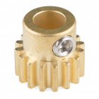
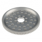
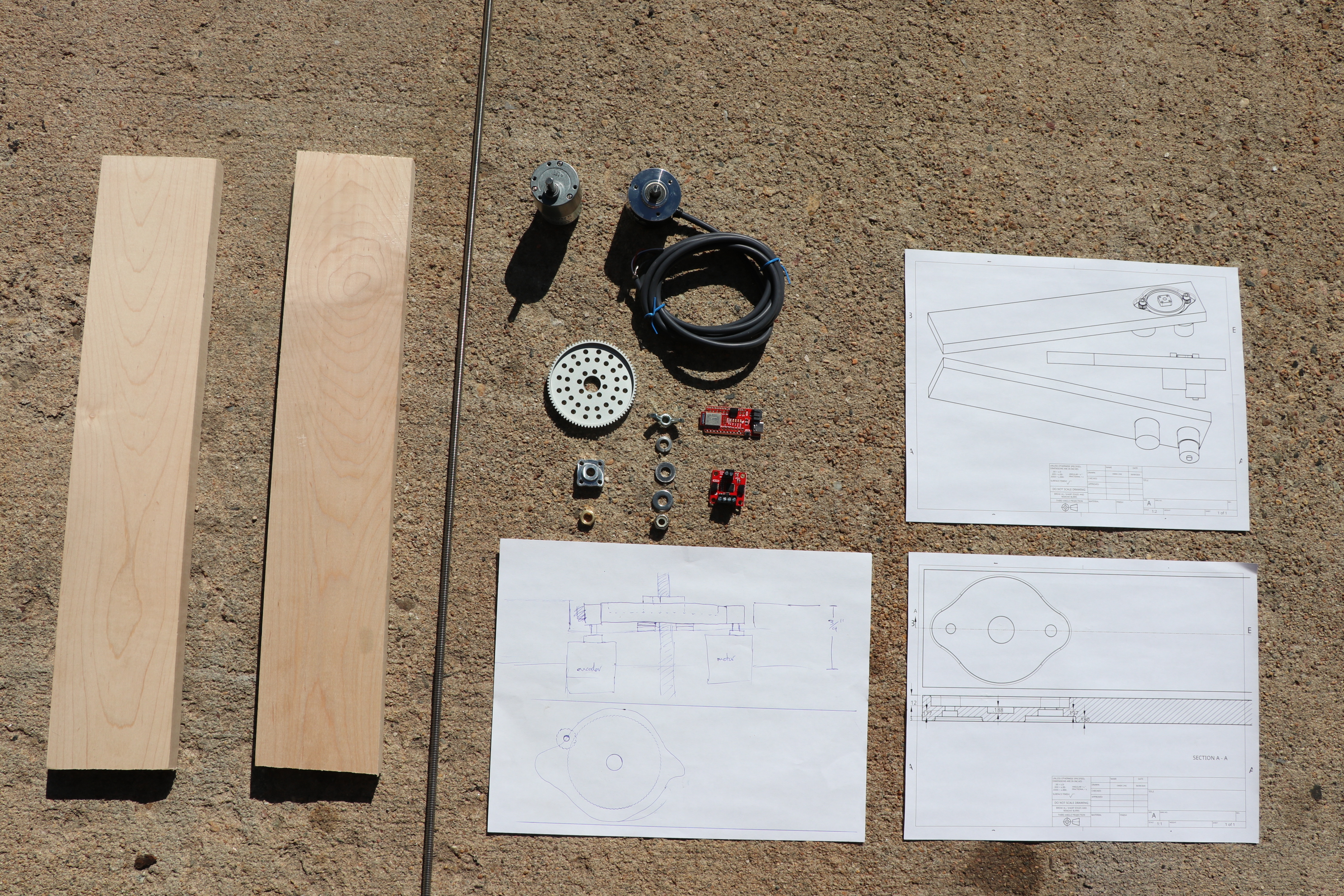
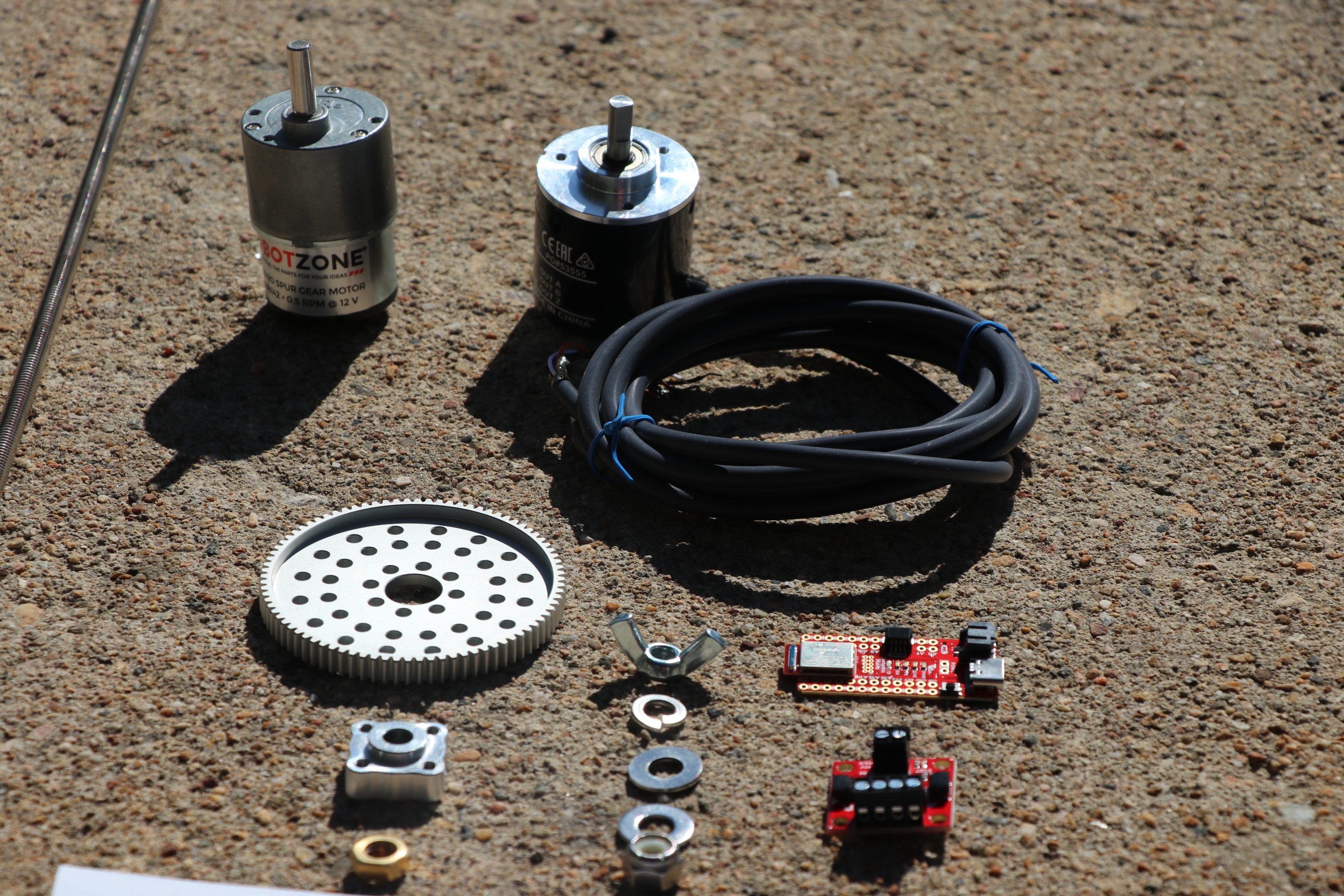
Usually my projects don't have a complicated mechanical aspect, but this one sure did. It was a good opportunity to try out some of the new robotics-focused parts that SparkFun offers like gears, axles, hubs, bearings, motors and encoders.
Here are the SparkFun parts that I used:


Two changes to this list are as follows:
- added a level shifter breakout for better compatibility with the encoder
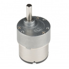
- changed the gearmotor to a 20 RPM version to fix a math mistake I made early in planning
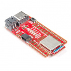
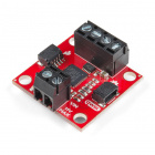
I chose the RedBoard Artemis Nano for its small footprint, great support for interrupts (for the encoder) and, admittedly, because I am fond of it. To drive the motor I decided to try out the Qwiic Motor Driver because it would be easy to hook up and get going.
I also needed a few miscellaneous pieces/parts from a hardware store:
- three-foot section of 1/4" stainless steel threaded rod
- one brass 1/4" nut
- one 1/4" nylock nut
- one 1/4" wing nut
- two 1/4" ID washers
- one 1/4" ID lock washer
- approximately 3.5' maple 1x4
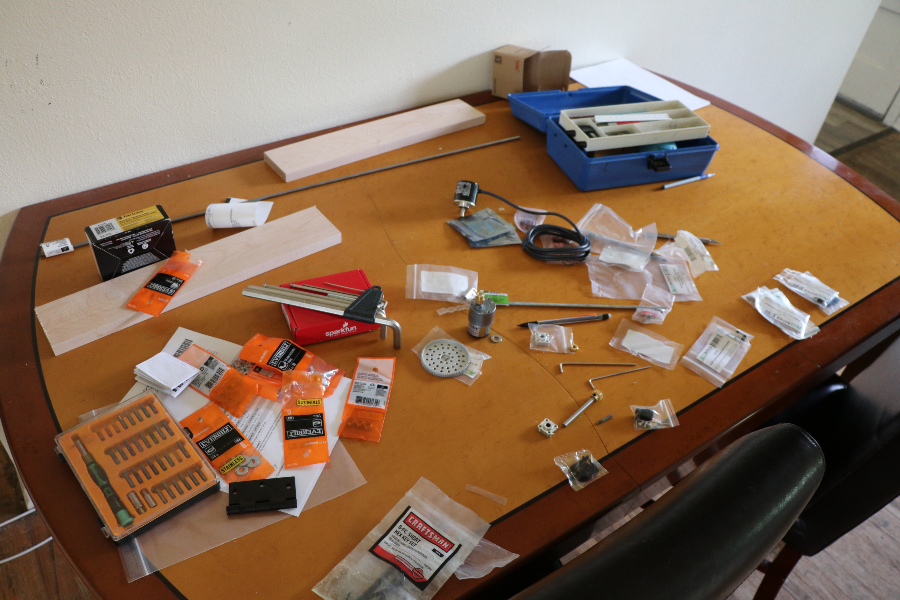
Figuring out how exactly to mount all these parts so that the gears would mesh correctly was perhaps the most challenging and time-consuming part of the project. I ended up making some rough 3D models of the main components and assembling them using OnShape (a very cool web-based 3D modeling application). Here are the public design files:
Build
I tried to dust off some old carpentry/fabrication skills and more or less discovered that dust is all they were to begin with. That being said here was my general process:
To build barn doors:
- Cut two 18" sections of maple 1x4 stock to serve as the barn doors.
- Within one section, mark a center line and a perpendicular hinge line about 1" from the end.
- Measure 14" from intersection and mark as center for the threaded rod.
- Use spray adhesive to locate top template over the threaded rod hole center.
- Drill small (1/8") holes where the pinion gear axles would go with a drill press (you can use a hand drill but make sure it is straight).
- Using those two holes, you can locate and adhere the bottom template.
- Use a router to route out the top template (pay attention to the correct depth [0.312"] and ignore the center hole).
- Flip over and drill the axle holes for the encoder/motor all the way through (5/16" or 3/8" drill bits work here).
- Working from the smallest shapes to the largest shapes, mill out the two levels for both the motor and encoder holes. Do the smaller ones first, because the template is destroyed in the process - pay attention to using the correct depth.
To build the drive mechanism:
- Use whatever means you can to affix the brass nut to the aluminum hub so that the hub can be screwed into the large drive gear (this one is hard, I used JB Weld, but broaching a hexagonal hole would be ideal).
To make the drive rod:
- Use a string or other method to trace out about 60 degrees worth of a 14" radius arc.
- With hands at either end of the threaded rod, use a pure twisting motion to bend it to match the 14" arc (the center will likely be the best section).
- Identify your best section and cut it out - the more you have, the longer you will be able to run the star tracker at a time.
Electronics hookup:
- Solder wires to the motor terminals.
- Connect motor wires into terminals A1 and A2 of the Qwiic Motor Driver.
- Connect your 8V to 11V DC power supply to the VIN terminals of the Motor Driver.
- Connect the Qwiic Motor Driver to the RedBoard Artemis Nano using a Qwiic Cable.
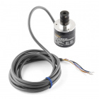
- Connect the encoder's brown wire to the same voltage supply as your motor.
- Connect the encoder's blue wire to GND on the Artemis Nano.
- Use your level shifting solution to connect the encoder's black and white wires to the Artemis on any pins you like (mosfet level shifters are recommended - I used voltage dividers because I was caught off guard and needed to whip something up fast. If you do this beware that the encoder has a 2k output impedance. I wound up using 2M and 1M resistors in my dividers).
- Power the Artemis Nano with a USB cable - or provide some other 5V source to VIN on the dev board.
Software
Though currently a work-in-progress, I plan to continue updating this project on GitHub: StarTracker.
Star trackers of this style don't necessarily even need software - a simple voltage regulator to adjust the motor's speed is often enough. In this case, however, I wanted to have a little fun and aim for high precision/reliability. For me that meant adding a feedback loop.
Earth's rotational rate is very stable (over the periods of time used to expose film for astrophotography), so you might wonder whether a control system is really necessary. In an idealized case you could set a motor off to do its own thing and it would also run at a constant rate. Any mismatch between the rate of the motor and the Earth's spin would be a constant error and stack up over time predictably. In fact, if you could get that difference to be small enough, then one could effectively hide it with other techniques (such as image stacking).
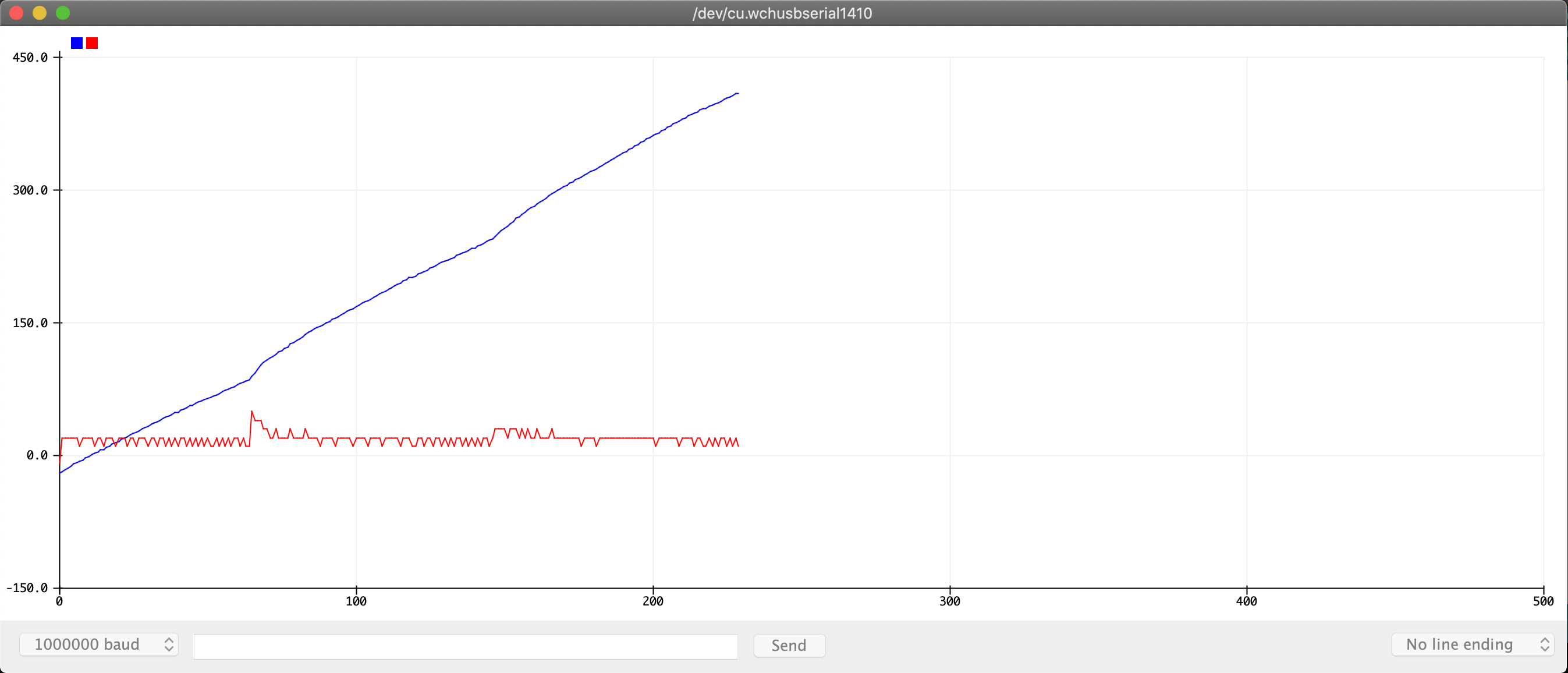
- Red: the measured error in rotational rate over time
- Blue: the overall positional error that has accumulated over time - you would observe this in an image as trails beginning to form behind the stars.
What happens when dust/dirt clogs up the system? When the battery voltage sags in cold weather? When a heavy camera/lens combination strains the drive system? In those cases there may be error that changes over time and is much harder to predict and account for. Covering these scenarios is what an active feedback loop does very well.
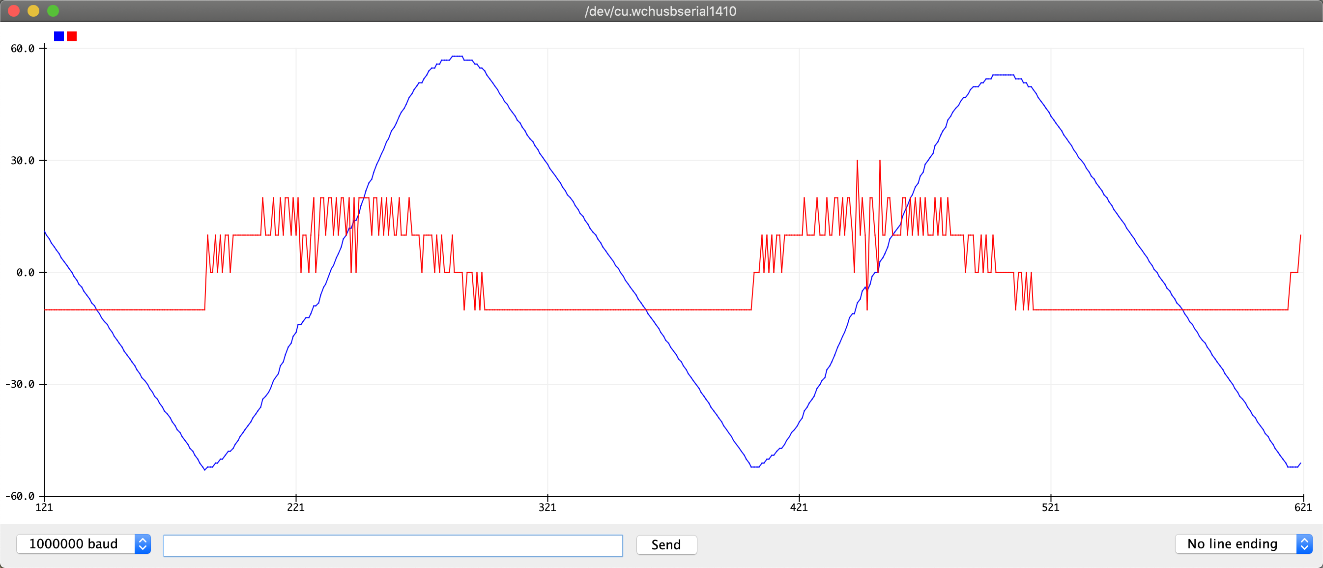
This time, as the overall position error increases, a proportional "restoring force" is applied to bring it back to zero (in practice this means changing the speed at which the motor is set to run). You can see that the error now oscillates around zero rather than growing infinitely. This is good, but we want the error to settle down to zero - that's where derivative feedback comes into play.
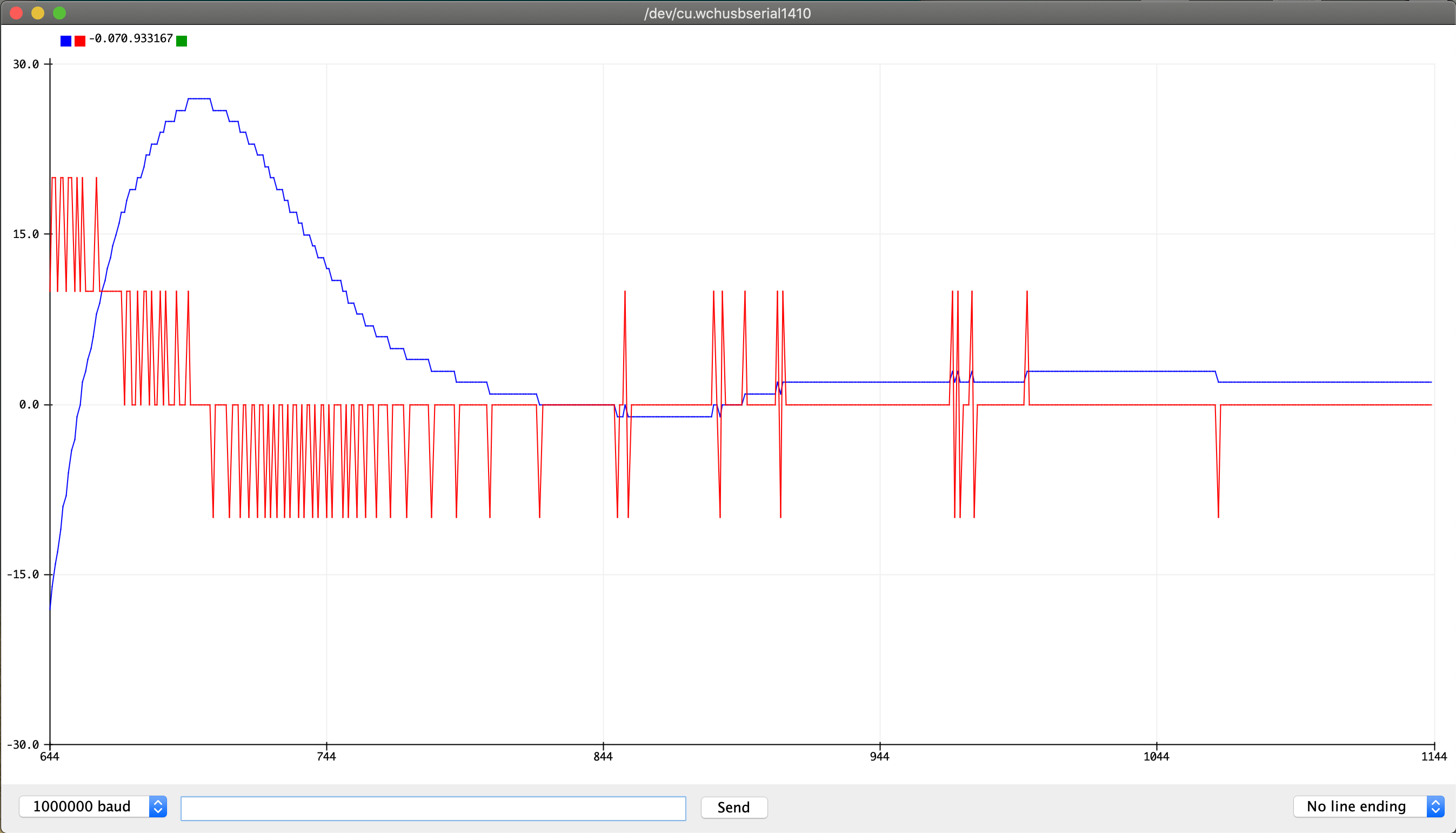
Finally, the error is controlled to zero. This is done by adding a "force" that counteracts motion toward the target.
Conclusion
Overall this was a fun way to combine my interests in astrophotography and control systems. The role of the latter in this project deserves a much more in-depth and precise examination, but it had to start somewhere! Hopefully this rig will be out there tracking stars very soon.

No comments:
Post a Comment