Jesse Brockmann is a senior software engineer with over 20 years of experience. Jesse works for a large corporation designing real-time simulation software, started programming on an Apple IIe at the age of six and has won several AVC event over the years. Jesse is also a SparkFun Ambassador. Make sure you read today's post to find out what he'll be up to next!
This is the second part of a multi-post series. If you would like to start from the beginning click here to see part one.
I would first like to respond to some comments I received on this project. I support and encourage the right to repair, and I can understand why people are upset with the current situation with newer equipment from John Deere or other companies. This mower was produced in a very different era and was very well documented by the owner's manual. For example, it included a complete circuit diagram with standard maintenance procedures and ways to fix common issues that an owner may have.
I’ve been making good progress on the mower project and I thought it was time for an update. A motor mount was fabricated and sprocket attached to the steering wheel. Size #25 chain is being used to connect the geared motor to the steering sprocket. The motor mount is notched to allow the chain tension to be adjusted.

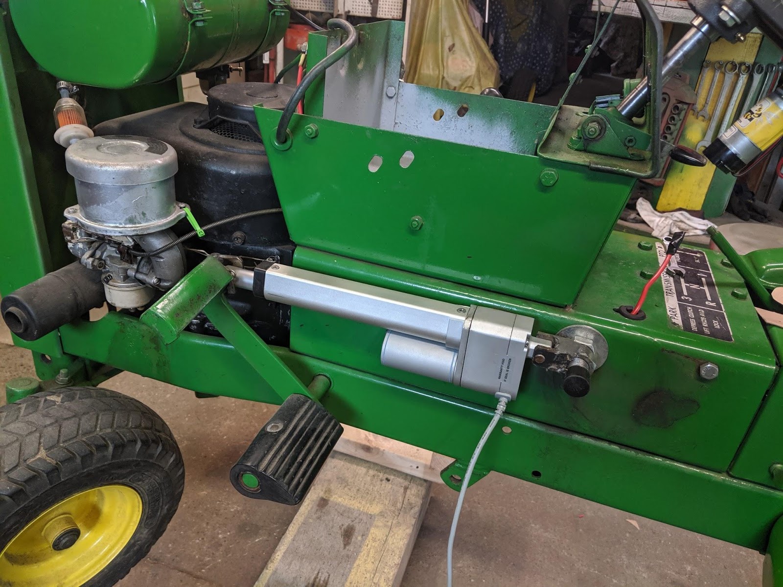
I also bought a linear actuator to control the brake/clutch mechanism. The linear actuator has a built-in potentiometer to provide feedback. This feedback will be used to set the end points for the actuator, so damage is not done to the brake pedal. The actuator has six inches of travel and 55 lbs of force for a margin of safety. As you can see, the mounting worked out well, as an existing hole was used and a threaded rod was run through that hole to mount the end of the actuator on a custom fabricated bracket.
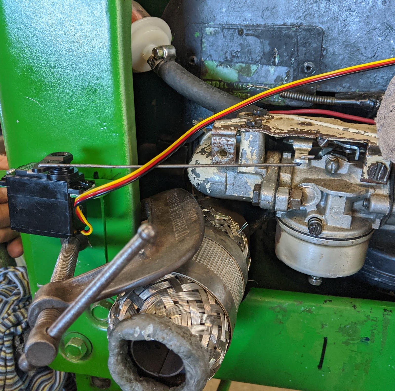
For the throttle, a servo was attached to the side of the tractor using a custom fabricated bracket. From the servo horn, a linkage was used to connect to the carburetor. This allows for full control of the throttle including the ability to kill the engine at very low throttle and choke for startup.
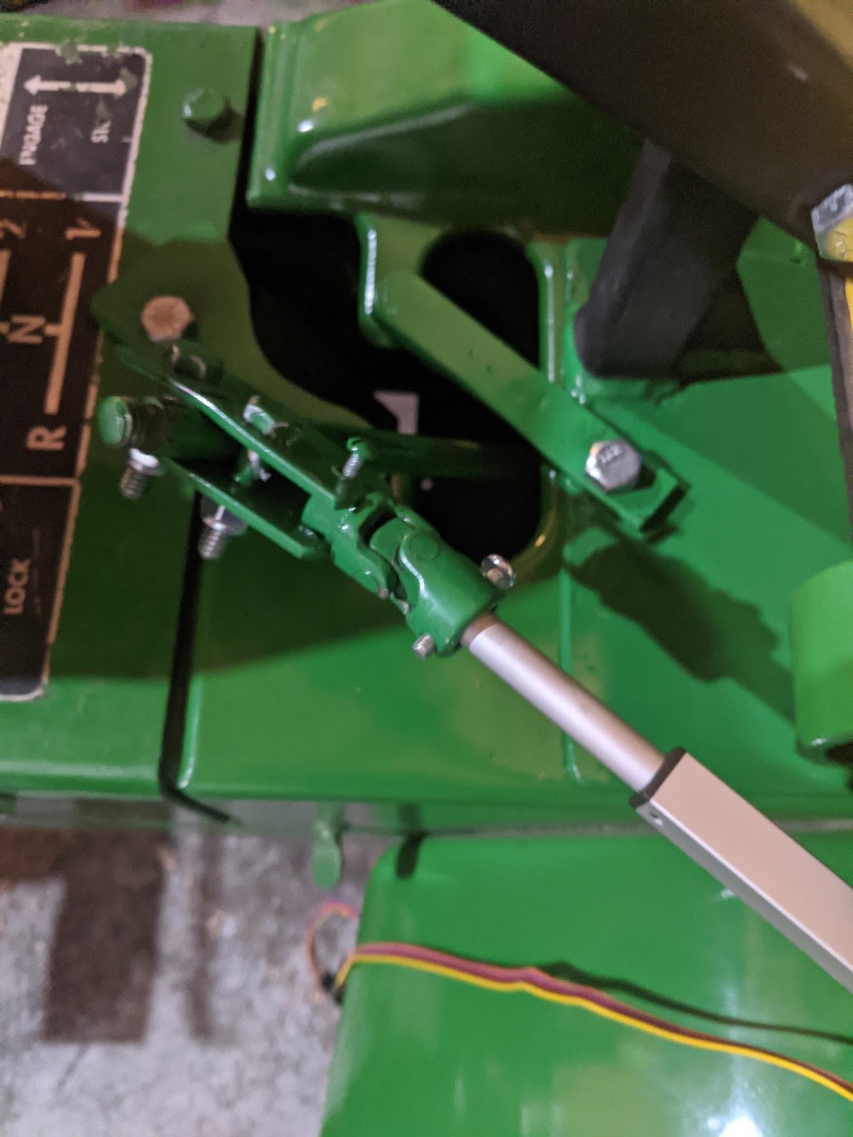
Another custom mount was fabricated to shift the mower between second gear, neutral and reverse. This completes the four major control systems required for the mower.
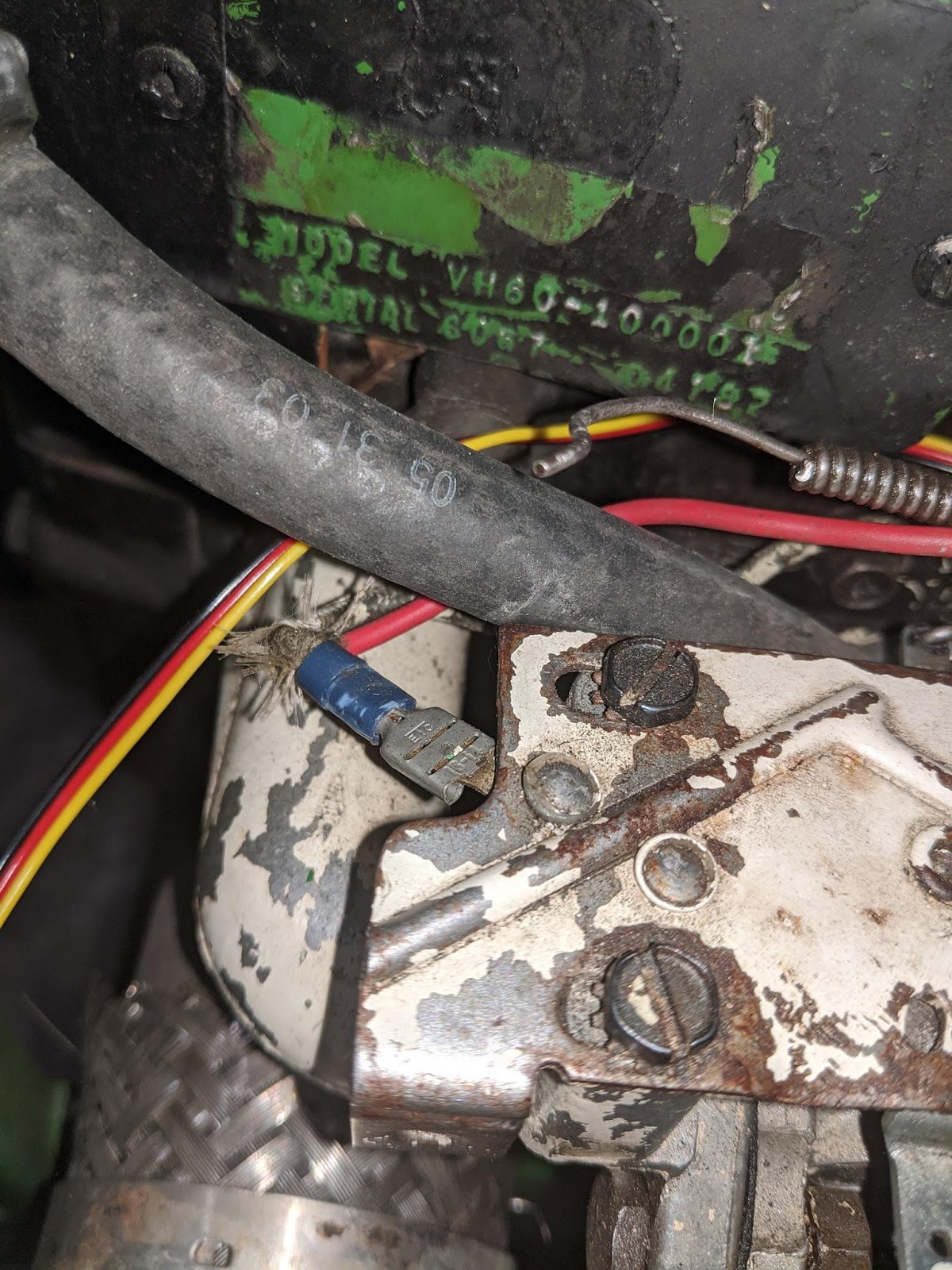
However, an extra safety system was added that allows the mower to be killed by shorting a wire that is part of the ignition system. This wire was routed up to the location where the controller will sit. The wire attaches to a relay on a normally closed connection. This means when the relay is not energized, the engine cannot run. This is a last line of safety in case the controller fails or power is lost.
A new circuit breaker was added to power the new control systems and wires run to the location of the controller. A fuse block provides power to the various circuits, and switches are used so the controller can be powered but leaves the motors disabled for testing.

I decided to do some testing before all the systems were ready; here is the result of my testing late last fall.
The project sat over the winter, but I started again this spring. The various systems I described above were fabricated and tested manually without the controller. I then started to work on the code for the overall system. The system will have the following modes: INIT, START, STOP, RUNNING, FAILSAFE, MANUAL and KILL.
Here is a table with the various modes and sub-systems. Any software connected to hardware should have various MODES and some rigid guidelines to avoid any catastrophic issues. This is no time to slack on your code!
| Mode | Brake | Throttle | Shifter | Steering | Kill Relay |
| INIT | ENGAUGED | KILL | DISABLED | DISABLED | OFF |
| STOP | ENGAUGED | Idle | Allow Change | DISABLED | ON |
| RUNNING | Controlled | Controlled | CONSTANT | Controlled | ON |
| START | ENGAUGED | Controlled | DISABLED | DISABLED | ON |
| FAILSAFE | ENGAUGED | Idle | CONSTANT | DISABLED | ON |
| KILL | NA | KILL | NA | NA | OFF |
| Manual | Controlled | Controlled | Controlled | Controlled | ON/OFF |
The FAILSAFE and KILL modes are used if some failure occurs. Depending on the nature of the failure, a determination is made if it’s a FAILSAFE or KILL failure. Loss of radio contact is a FAILSAFE failure, but any communication failure with the controllers is a KILL failure. Other failure modes will be added as needed, such as low input voltage, temperature too high on some sub-system, over current on steering motor controller, etc.
I think most of these modes are easy to explain. MANUAL mode exists for testing, and will allow for testing in ways the other modes will not allow. My end customer for this mower will not have access to this mode.
From each of the above modes, only certain other modes can be intentionally reached except for KILL. Here is what switching to different modes looks like.
INIT -> STOP (Automatic)
STOP -> MANUAL/START/RUNNING
RUNNING -> STOP
MANUAL -> STOP
FAILSAFE -> STOP
KILL -> NONE
FAILSAFE mode is possible from any mode other than FAILSAFE or KILL, but the controller decides when it is activated. If the FAILSAFE condition is resolved, then switching to STOP is allowed.
At this point, all that is left is to test the above logic in standalone mode off the mower, and make 100 percent sure that the above logic table is followed and no crashes or weird behaviors occur. I’ve certainly found and fixed issues already, such as the brake not being engaged when switching from RUNNING to STOP. This would mean I could not stop the mower without switching to RUNNING mode again and that could lead to a runaway mower.
Once standalone mode is working, I will start testing the various control systems in isolation and then finally test the entire system on the mower. Please stay tuned for the final write-up on this project (hopefully in a month or two), and hear details about my next big project: a remote control/autonomous electric go-kart!
As a thank you for reading this far, I would like to let you know I have a special promo code you can use to get 10% off any SparkFun Original product. Just use ORIGINALRED2020 during checkout. This code is good through the end of 2020, but can only be used once per customer. Thanks for reading - I hope I can start attending STEM shows next year and show off my hard work on this and other projects I have been working on.
No comments:
Post a Comment